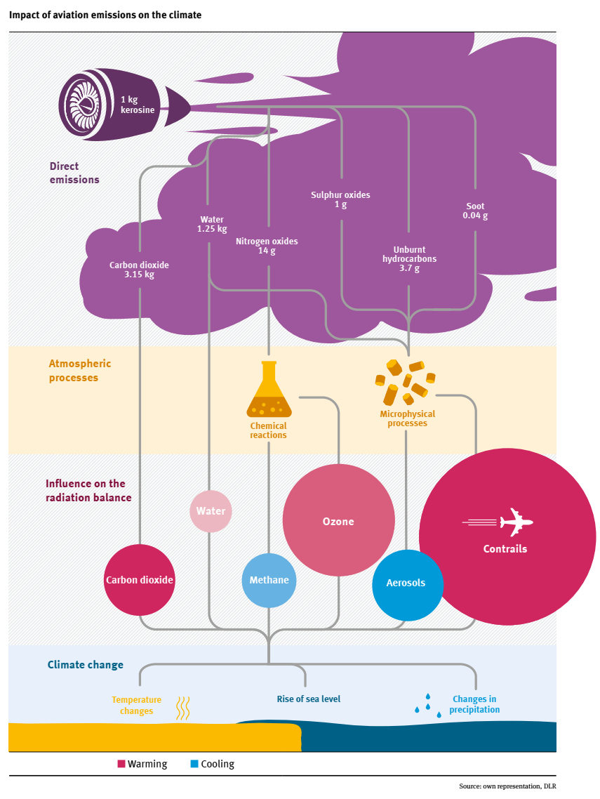
During flight, an aircraft not only emits carbon dioxide (CO2) but also a number of other trace substances. Both have a negative impact on the climate and lead to global warming. These include water (H2O), nitrogen oxides (NOx), sulphate, soot and unburnt hydrocarbons (see figure below). These emissions either have a direct influence on the radiation balance of the atmosphere (CO2, H2O) or influence the climate indirectly via chemical reactions or microphysical processes. The emission of NOx has no direct influence on the climate, but leads to a concentration change of ozone (O3) and methane (CH4). The emission of many other trace substances causes the formation and properties of clouds and aerosols through microphysical processes. While CO2, H2O, O3, and contrails lead to a warming of the climate, the reduction of CH4 and aerosols leads to a cooling.
Background
Climate impact of flight operation
For the comprehensive ecological assessment of individual aircraft concepts, it is important to include the impacts of the different climate relevant chemical species (e.g CO2, O3, Contrails). In EXACT, we are assessing the climate impact of in-flight emissions using the climate response model AirClim, with the flight trajectories from the tool GRIDLAB.
Life cycle assessment for ground-based processes
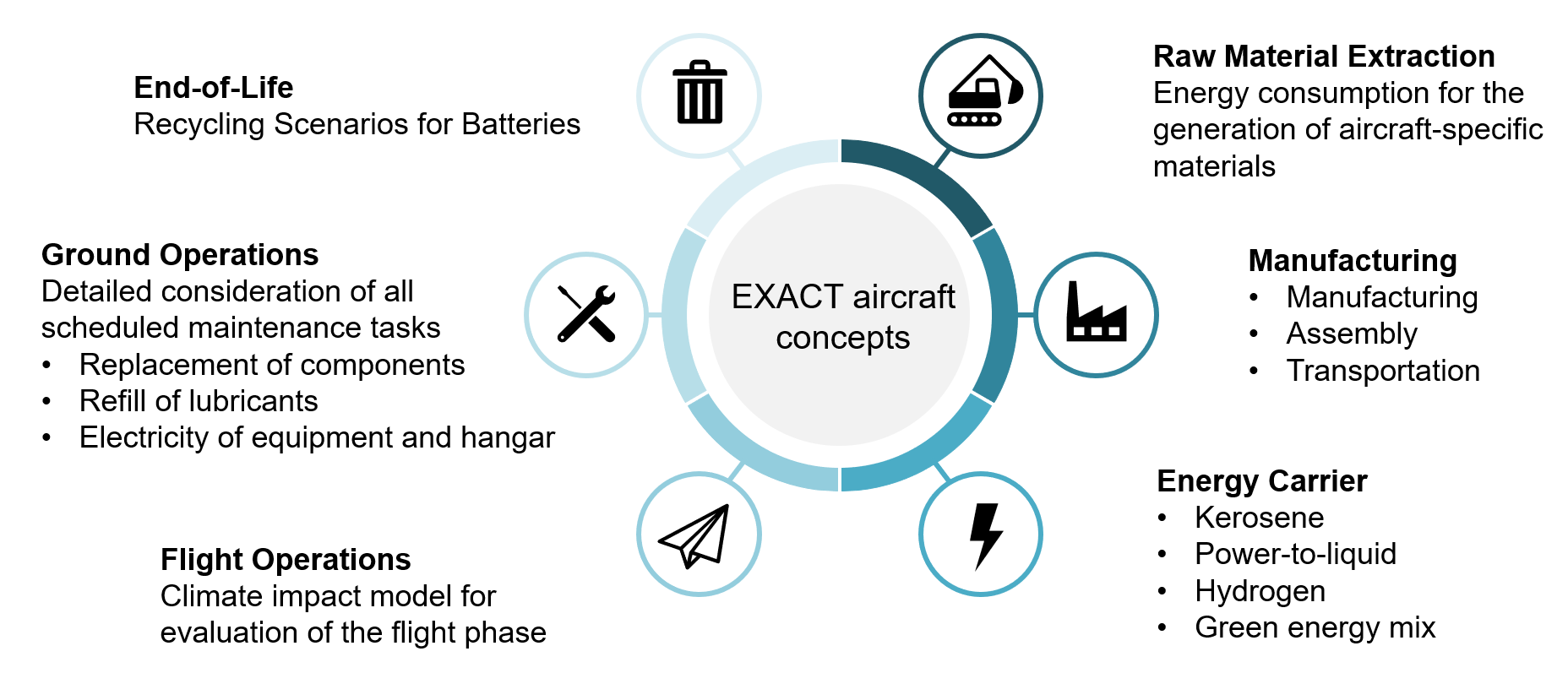
In EXACT, the entire life cycle of the aircraft is covered – from raw material extraction to the aircraft’s end-of-life. The life cycle assessment is applied for all ground-based impacts and coupled with the climate impact assessment of the flight operations.
For calculating these ground-based ecological effects, we are using a standardised life cycle assessment method: We examine the environmental effects of each life cycle phase in detail to understand in full, which ecological aspects can be achieved. This is a precondition for a comparing of different aircraft designs from various perspectives. Life Cycle Assessment is defined as the evaluation of the environmental impacts of a product or a product system across all life cycle phases. Life Cycle
Assessment is generally divided into the following four steps:
- Goal and scope definition
- Life Cycle Inventory analysis
- Life Cycle Impact Assessment
- Interpretation
The Life Cycle Assessment undergoes several phases. In the initial phase, the analysis’ goal and scope are defined, including system boundaries and a functional unit for a detailed product description. The data collection phase identifies all processes of a product system and gathers resources, materials, and emissions. The impact assessment translates the inventory into environmental impacts using selected impact assessment methods. The results are multiplied by impact factors and sorted into impact categories. In the final phase, the results are interpreted, conclusions are drawn, and recommendations are derived, assessing the study’s completeness based on the defined goals and limitations.
Environmental assessment of future propulsion systems
A comprehensive examination of the ground-based impacts is conducted for components that are part of the new drive system. This primarily encompasses the fuel cell system and the batteries. A specific mass and material breakdown of all subcomponents is essential, particularly for production purposes. Furthermore, the maintenance of these components is evaluated from an ecological standpoint, employing detailed expertise, in order to identify potential opportunities for the ecological improvement of individual maintenance tasks. In addition to CO2 emissions, water and use of other resources as well as the use of rare earths are considered. This is especially important for battery electric concepts such as the Plug-In-Hybrid (PHEP) where a very high battery recycling rate and the recovery of materials is one key ecological aspect.
Economics of Aviation
In today’s rapidly evolving aviation landscape, the aspiration for sustainability and innovation drives the exploration of new aircraft concepts. However, alongside technological advancements, understanding the economic implications of these innovations is key. Let’s delve into why analyzing the economics of new aircraft concepts is crucial, how this is traditionally approached, what the challenges faced are, and how the evolving methods shape the future of aviation economics.
Why economically analyze new aircraft concepts?
As the aviation industry seeks to mitigate its environmental impact and to adapt to evolving market demands, the development of new aircraft concepts becomes imperative. Understanding the economic viability of these concepts is essential for airlines and manufacturers alike. It allows stakeholders to assess performance, evaluate investment decisions, and ensure long-term sustainability. In this pursuit, Direct Operating Cost (DOC) methods and Lifecycle Cost-Benefit (LCCB) analysis emerge as indispensable tools, providing insights into the economic feasibility of new aircraft concepts.
Current approaches and challenges
Traditionally, DOC methods have served as the cornerstone for evaluating aircraft operating costs. However, applying these methods to new concepts presents challenges due to their reliance on historical data and conventional aircraft types. As the aviation industry embraces innovative propulsion technologies such as hydrogen and electrification, conventional methods struggle to accurately assess their economic impact. Challenges such as uncertainty and extrapolation issues hinder the effective evaluation of new aircraft concepts.
Evolving Methods: DOC and LCCB Analysis
To address these challenges, a paradigm shift towards more comprehensive and nuanced analysis methods is underway. Adaptations of DOC methods, incorporating factors like system electrification and battery characteristics, aim to provide more accurate cost estimations for new aircraft concepts. Additionally, Lifecycle Cost-Benefit (LCCB) analysis emerges as a holistic approach, considering all costs and revenues over an aircraft’s lifecycle. Net present value, within the LCCB framework, serves as a metric to assess the individual cost aspects per year while also incorporating potential revenues. This integrated approach offers a more nuanced understanding of the economic performance of new aircraft concepts, aiding stakeholders in informed decision-making.
Integrating Global Impact Assessment
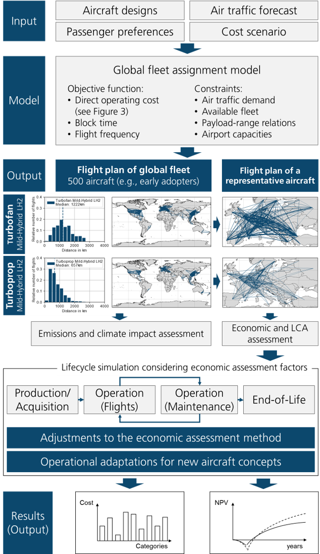
In our quest for comprehensive analysis, we incorporate a global impact assessment into our methodology. This assessment relies on carefully crafted operational scenarios tailored to the aircraft being analysed. We use a global fleet allocation model to calculate these scenarios, examining both turbofan and turboprop aircraft variants. To delve deeper into the economic landscape, we use LYFE, a modular aircraft lifecycle simulation tool. Through discrete event simulation, LYFE meticulously examines each phase of the aircraft lifecycle, capturing attributes such as duration, cost, revenue and more. This integrated approach allows us to compare different aircraft concepts, providing invaluable insight into their economic performance and helping stakeholders make informed decisions.
Conclusion: Navigating Towards Economic Sustainability
In navigating the complexities of new aircraft concepts, understanding their economic implications is crucial. By embracing innovative analysis methods like DOC adaptations and LCCB analysis, stakeholders can gain deeper insights into the economic feasibility of these concepts. Ultimately, this holistic approach paves the way towards economic sustainability in aviation, ensuring that innovation aligns with financial viability and environmental responsibility.
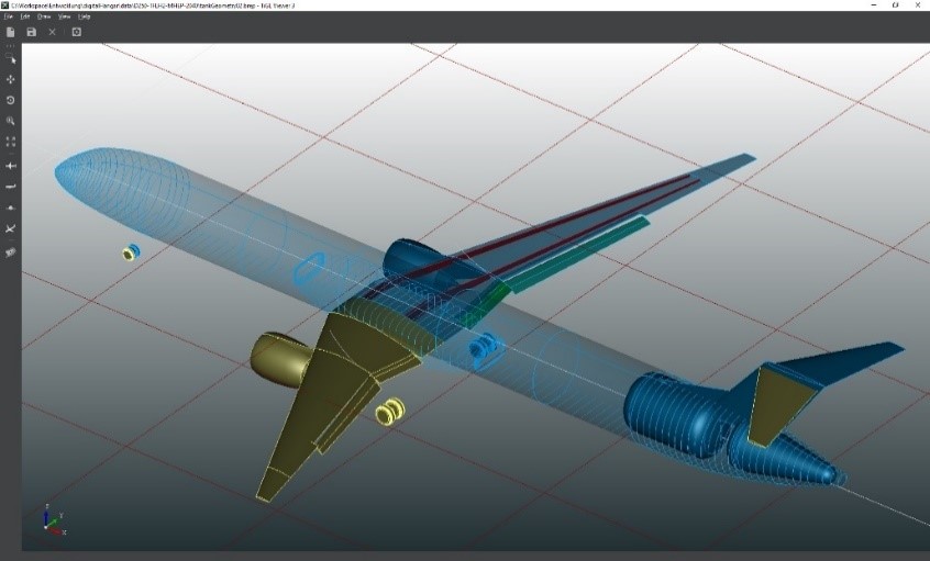
Aircraft configuration
In the EXACT 1 project, the focus was on short- and medium range (SMR) concepts, since this range category will be most suited to employ alternative propulsion architectures. This is due to the lower overall energy demand on those missions. However, this range class is responsible only for approximately half of the total aviation emissions. Since long-range flights contribute the other half, a complete ecologic and economic assessment of aviation as a whole requires an investigation on the aircraft carrying out these longer flights. In EXACT2 Mid- and Long Range are considered with both synthetic kerosene and liquid hydrogen as an energy carrier. Due to increasing travel demand and increasing airport capacity limitations EXACT2 adjusts its aircraft sizes appropriately. In EXACT 1 and EXACT 2, the aircraft configurations considered are evolutions of the current state of the art tube and wing aircraft. Since climate impact reduction effort is mostly about changing the energy carrier and propulsion system, this helps to reduce uncertainty while still reaching a significant cut in emissions.
Potential Climate Neutral Propulsion Systems
The most promising technologies are:
- Energy carrier: The energy carrier is the central technology which determines both, the carbon dioxide (CO2) reduction potential, as well as the economic viability of the overall system. Both aspects are mostly dependent on boundary conditions of the energy carrier production and on the related aircraft behavior. Our EXACT study shows, the following energy carriers are promising: liquid hydrogen (LH2), synthetic kerosene and electricity stored in batteries.
- LH2: The biggest advantage of LH2 is its high production efficiency and hence potentially low prices compared to synthetic kerosene. Furthermore, it’s very high gravimetric energy density (about one third of the mass per energy compared to kerosene) renders the application of LH2 in aviation promising. Some economical disadvantages and technical challenges related to high storage volume requirements (about four times the volume compared to kerosene), cryogenic temperatures (about -253°C) and conditioning of LH2 have yet to be overcome.
- Synthetic kerosene: This energy carrier has the lowest implications at aircraft and airport level, which can be considered as its main advantage. Fossil-based kerosene can simply be replaced by synthetic kerosene. Just minor changes to aircraft and ground based infrastructure are required. However, the production process is currently rather inefficient which requires more primary climate-neutral electric energy compared to the production of LH2. Moreover, a renewable carbon source (e.g. direct air capturing) is required for synthetic kerosene to be climate-neutral, leading to higher production costs and high economic uncertainties.
- Batteries: Compared to LH2 und synthetic kerosene, direct use of electricity is the cheapest energy carrier, even including the production cost of the batteries. Furthermore, the efficiency at aircraft level is significantly higher. However, due to the low gravimetric energy density (about 30 times the mass per energy compared to kerosene), the flight distances that can be covered by battery-electric aircraft are very limited which reduces the overall climate impact reduction potential. Yet, this drawback can be diminished by hybrid applications like the plug-in hybrid architecture shown below. Key conditions for ecological and economic success of this energy carrier are sophisticated second battery life approaches and rigorous recycling of batteries.
- Power provider: The power provider is one of the most important technologies influencing non-CO2 climate impacts caused by nitrogen oxides (NOx) and persistent contrails. To convert the stored energy power to shaft power, three general possibilities and their combinations have been considered relevant in EXACT:
- Gas Turbines: Gas turbines achieve very high efficiencies for high power classes. Furthermore, the gravimetric and volumetric power density of the gas-turbine is very high.The primary drawback from the economic stand point is the high production cost. Furthermore, from the ecological point of view, the NOx and soot (for kerosene) emissions from the combustion cause non-CO2 effects. However, this may potentially be reduced by new radically low NOx combustion chambers.
- Proton-Exchange Membrane (PEM) Fuel-Cell – Electric-Motor: Fuel Cells (PEMFC) are a promising technology for future low-emission aircraft. They can be used to convert hydrogen into electric power to use for electrically driven propellers or for supplying energy to the onboard systems.For the propulsion of mid- to long-range aircraft, hydrogen combustion is superior compared to fuel cells due to the higher specific power of large gas turbines.For regional aircraft, fuel cell-based propulsion is an attractive option. Fuel cells offer greater efficiency compared to small turboprop engines and do not produce carbon or nitrogen oxide emissions during flight. This makes them a promising technology for the future of sustainable aviation.The PEM fuel-cell achieves very high efficiencies rather independently of the power class. This makes it a very promising power provider for smaller aircraft (regional class) or in hybrid architectures such as the Mild-Hybrid-Electric-Propulsion (MHEP) concept. Another strong advantage is the absence of NOx emissions. However, the gravimetric power density is rather low (low power for high mass) and due to the low temperature exhaust heat, cooling is challenging especially during take-off at high ambient temperatures.
- Battery – Electric-Motor:
Electrified aircraft propulsion systems represent a transformative shift in aviation as it enhances efficiency, lowers emissions as well as noise and reduces the aircraft’s reliance on fossil fuels.Novel aircraft topologies employ electric motors powered by batteries, fuel cells or hybrid systems, enabling novel aircraft designs such as distributed propulsion.Challenges include component power density, reliability and aviation compatibility with regards to safety and the influence of environmental conditions on the design. Achieving this technological transformation will require interdisciplinary collaboration, innovation in drivetrain technology, and advances in power- and thermal management.In EXACT 2, an electric drivetrain for an aircraft is designed, which focuses on electric machines and power electronics. It minimises electromagnetic interferences (EMI) and acoustic noise propagation, while conducting a system safety analysis in alignment with relevant aeronautical certification specifications. These are further extended in accordance with the electrification of drivetrain.The battery electric operation has exceptional efficiencies and no local emissions. However, the central drawback is the low gravimetric energy density which is limiting the economic viability of fully-electric ranges to few hundred kilometers. Nevertheless, if combined with a gas-turbine in a Plug-In Hybrid (PHEP) architecture, this drawback can be mitigated.
- Thrust provider: Ducted fans and propellers are considered as thrust providers. In order to increase propulsive efficiency, the propulsion system must capture a larger volume of air and apply a low acceleration to the air passing through the propulsion unit. This leads to propulsion systems of larger diameter. Rotors fully enclosed in engine nacelles (ducted fan) are perfectly suited for lower engine diameters and transonic flight speeds. This is preferable in terms of operating costs and the passenger’s value of time. Larger diameter nacelles have much larger drag and weight, which quickly can become a disadvantage that need to be considered in aircraft design. For very large propulsion systems, omitting the nacelle and using propellers or rotors provides the best overall efficiency. Furthermore, the reduced speed of the propeller aircraft leads to lower optimal flight levels and in this way reduces the non-CO2 climate impact, which is smaller in lower altitudes.Challenges connected to these unshrouded devices are noise and vibrations as well as structural loads and the impact on flight mechanics. For maximum efficiency and low noise levels, low speeds of rotation are needed, requiring turboshaft engines or electric motors of low revolutions per minute (RPM) and high torque and often an intermediate gearbox to adapt the propulsor to the shaft power.
- Operational strategy: How to operate the aircraft is not just a key element for hybrid propulsion concepts but also central to reduce the overall non-CO2 climate impact. The benefits of the MHEP and PHEP concepts lay especially in the operational strategy, leading to the ideal synergetic interaction between the different power providers on board.
Collaborative Engineering Framework
The aircraft industry must continuously innovate to meet the demands for advanced, cost-effective, and high-performance aircraft, often within increasingly shorter development timelines. Therefore, enhancing the effectiveness and efficiency of collaboration among aircraft design experts is a crucial aircraft development process. This leads to the need for a methodology to automate and accelerate the design process by setting a common standard and digitizing the process.
The Collaborative Engineering Framework (CEF) built for/within EXACT, provides a solution by digitizing and standardizing the integrated design process. This can significantly reduce integration problems and has the potential to accelerate the exploration of the design space. The CEF consists of three main platforms:
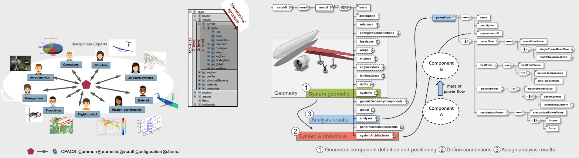
CPACS: Large-scale multi-disciplinary design analysis and optimization (MDAO) campaigns for complex systems design face the challenge that disciplines and experts might be organizationally and/or geographically distributed. This results in data interface and exchange issues which can be partly overcome by adopting collaborative MDAO techniques. Using a Central Data Schema (CDS) ensures that all disciplines “speak the same language” and enables implementation and reuse of disciplines in collaborative MDAO workflows. The Common Parametric Aircraft Configuration Schema (CPACS) is an example of such a CDS. It is an open-source XML-based format for exchanging aircraft design data which has been applied successfully in many projects across disciplines and organizations. For more than two decades, CPACS has supported collaborative aircraft design by providing an open, central data model that serves as a common language. During this time, CPACS has been continuously enhanced to meet changing design requirements. With the recent interest of the aviation community in alternative propulsion and onboard system architectures, such as hybrid electric propulsion concepts, one of the latest additions to CPACS is an integrated system definition within the data schema. It allows for the explicit definition of aircraft systems and facilitates the aircraft design process between system experts and overall aircraft designers.
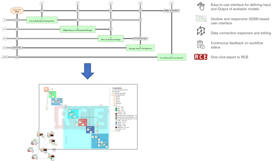
MDAX: In an aircraft design process, the integration of different disciplines into a single/holistic design process, their interaction with each other, and the exchange of diverse data-sets leads to time and resource-intensive workflow development processes. The MDO Workflow Design Accelerator (MDAx) is a collaborative Multidisciplinary Design Analysis and Optimization (MDAO) workflow designing platform, we developed to make the process easier and faster. To describe the workflows and provide additional operations, MDAx makes use of the eXtended Design Structure Matrix (XDSM) representation. This leads to an executable workflow, which can be exported to process integration platforms like RCE, OpenMDAO etc. It provides efficient methods to inspect and explore the different disciplinary components of the workflow and their data couplings. The latest additions to the environment include automatic minimisation of feedback, modelling sub-workflows as components, value-based identification of variables and discipline (de)activation.
RCE: Remote Component Environment (RCE), is another platform we developed within the DLR, which in combination with a server network allows the disciplinary experts to share their competencies as engineering services, while maintaining control over proprietary software. Using RCE, collaborative simulation workflows are designed and executed to investigate design space and evaluate a wide range of configurations and interesting concepts. The generated results are then stored in a formal and centralised storage location, from where they can be retrieved and inspected by all project participants.